Become a leader in the IoT community!
Join our community of embedded and IoT practitioners to contribute experience, learn new skills and collaborate with other developers with complementary skillsets.


Join our community of embedded and IoT practitioners to contribute experience, learn new skills and collaborate with other developers with complementary skillsets.


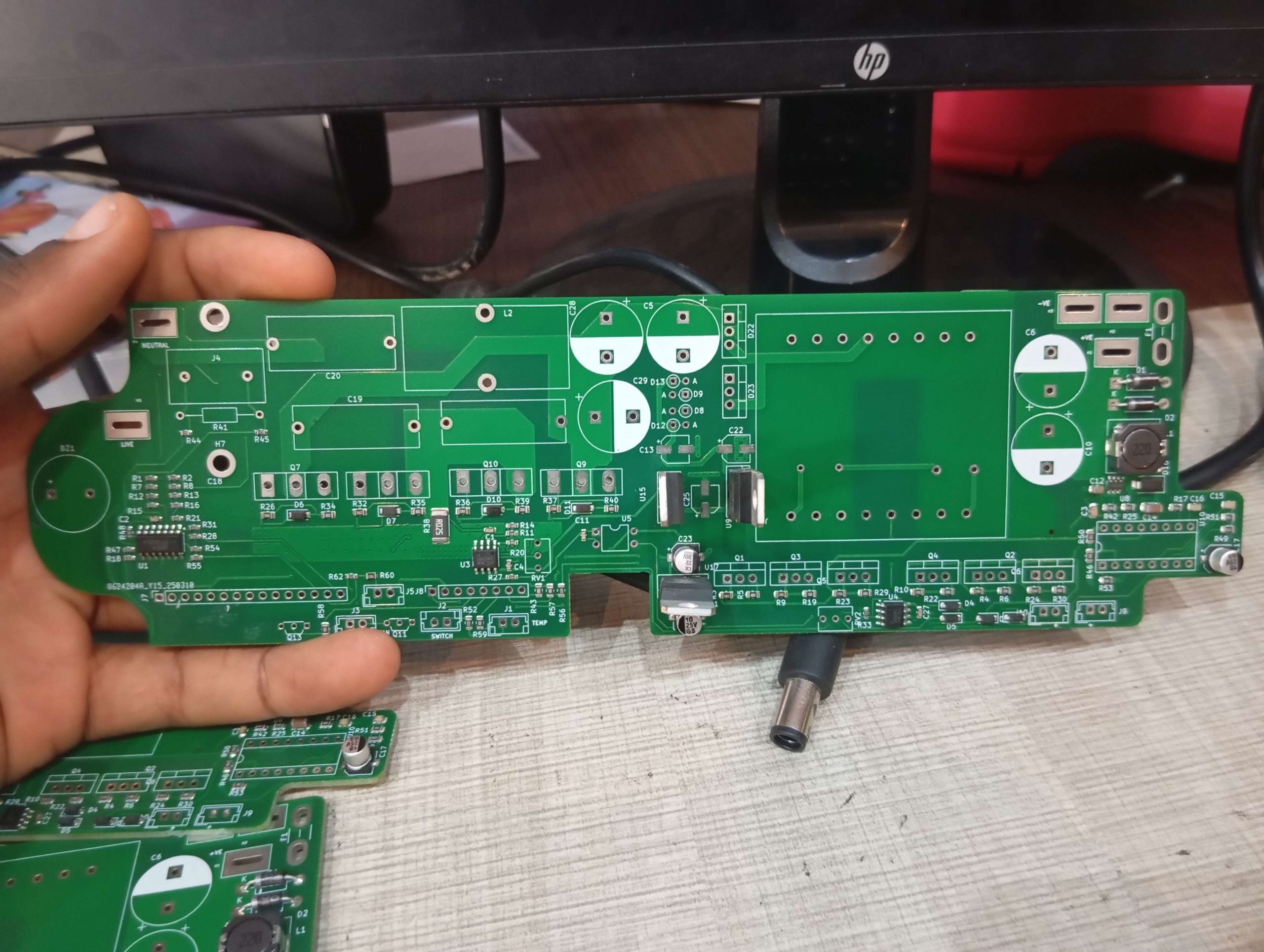
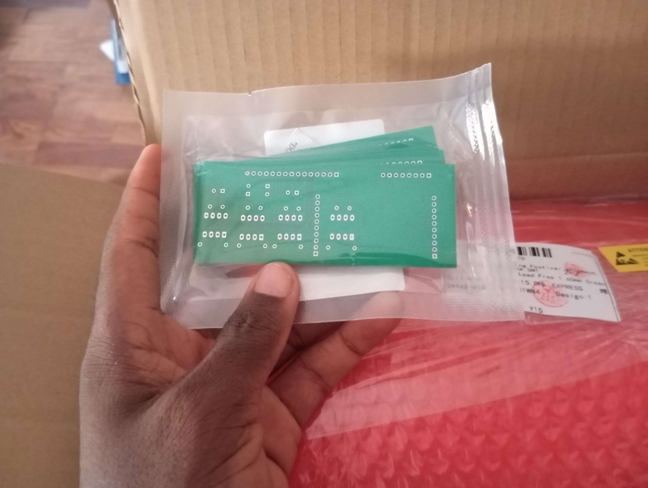
High frequency inverter board came in yesterday. The major adjustment on this is the short circuit protection using shunt current sensing resistor and optocoupler, also proper filtering of the high voltage was done also, I am going to carry out some test on the device this weekend


Very neat. What is the purpose of some of the really large traces and/or fill zones? Also, did you consider filling the whole unused area with a ground plane? It may work fine, but that is supposed to be good practice.
most probably it’s passing high current
This one currently has high current passing through it
Yeah you are right
I did fill the unused area with ground plane, there are actually two gnds on the bord
For now I’m just testing the circuitry connected to the first gnd, I’ll drop more updates
Sounds good on both counts. How is it working out?
CONTRIBUTE TO THIS THREAD