Become a leader in the IoT community!
Join our community of embedded and IoT practitioners to contribute experience, learn new skills and collaborate with other developers with complementary skillsets.

Join our community of embedded and IoT practitioners to contribute experience, learn new skills and collaborate with other developers with complementary skillsets.


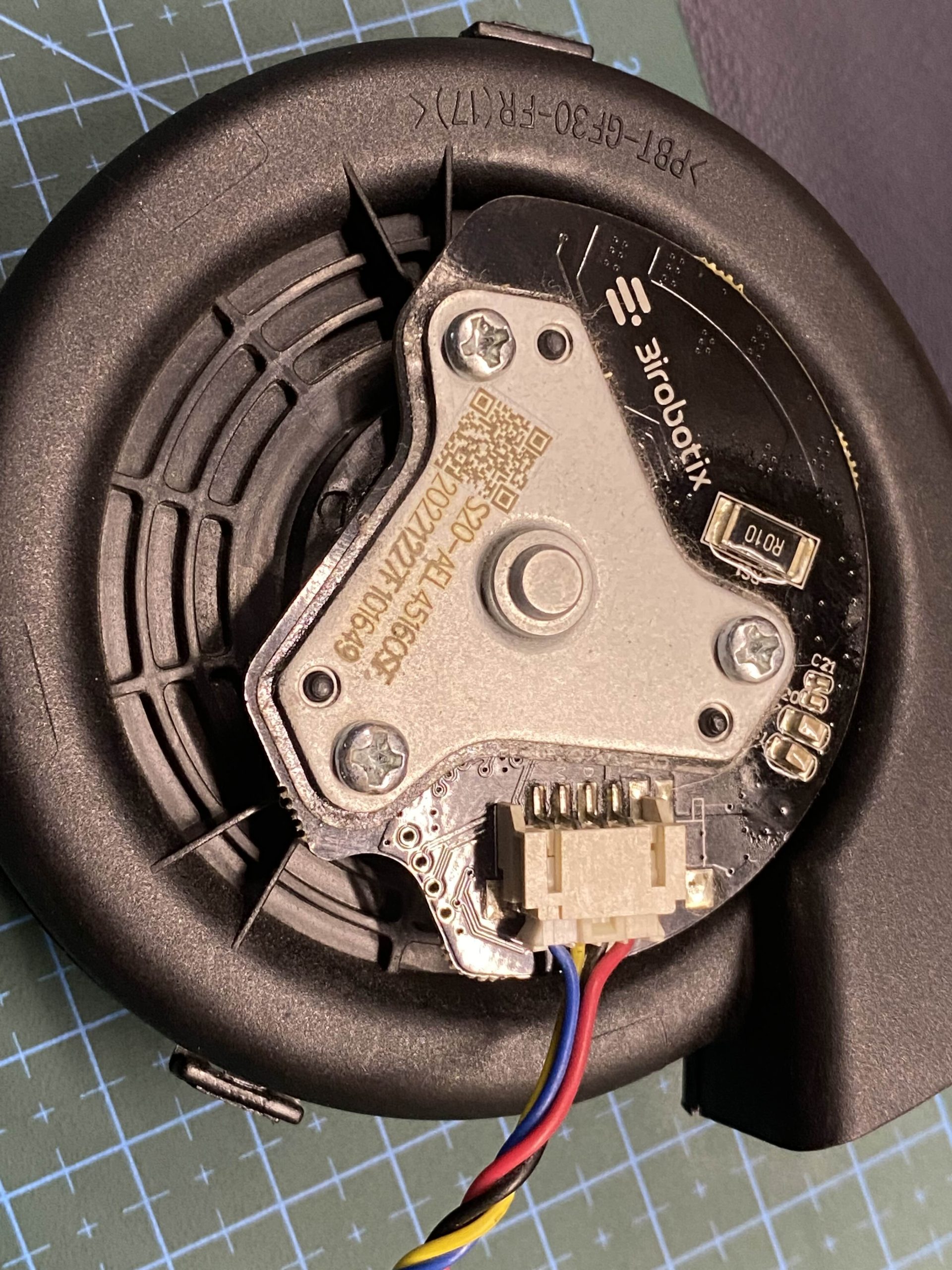
This is a vacuum suction motor from vacuum robot that am trying to interface with Raspberry Pi. It has 4 wires and am not able to get it working. Any suggestions on wiring


Hi, given the four wires, perhaps it is controlled like a BLDC (brushless DC motor). I haven’t worked with them much if any, but I believe they typically have three coils that need to be energized, and maybe the fourth wire is a ground? That might be a good place to start, and controllers for such devices are readily available.
A stepper comes to mind too, but those are generally lower speed so a vacuum would make less sense, but the way they work is similar.
So maybe search for soemthing like “BLDC control with Raspberry Pi?”
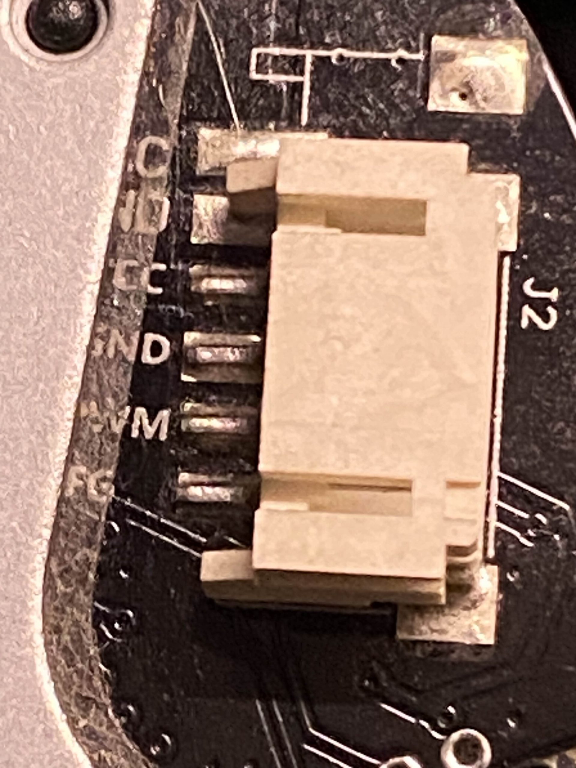
If you look at the 2nd picture, it is marked as VCC, GND, PWM and *fg. I tried with first 3 pins and gave rpi pwm but didn’t work. I think the 4th one is enable pin. But tried supplying 3.3v constant on both pwm and enable bot that didn’t work. Assuming most BLDC are 5v, I tried 5v as well and that didn’t work.
Most likely there is a sequence I should follow or the driver expects a particular frequency in pwm
Ah, OK, well that makes sense then that it would need PWM.
Did you test the motor in its native configuration before hacking it? I always try to do that to make sure I’m not trying to beat a dead horse so to speak (wow, that is a rather cruel idiom, not that I type it out).
Wonder what the input/voltage current requirements are?
Also, PWM can have different duty cycles, so maybe consider trying different timings? For that matter, something like a hobby servo uses what’s generally called a PWM input, but it’s actually a bit different than normal PWM from my understanding timing-wise. Perhaps that woudl be another avenue of experimentation.
Good luck, I am curious to see what you find out!
I tried different PWM duty cycles from 20 to 50K Hz but no luck. My doubt is whether there is a sequence to follow. My next test is with frequency varying PWM. I’ll keep updating here about the progress.
CONTRIBUTE TO THIS THREAD