Become a leader in the IoT community!
Join our community of embedded and IoT practitioners to contribute experience, learn new skills and collaborate with other developers with complementary skillsets.


Join our community of embedded and IoT practitioners to contribute experience, learn new skills and collaborate with other developers with complementary skillsets.


Hi everyone,
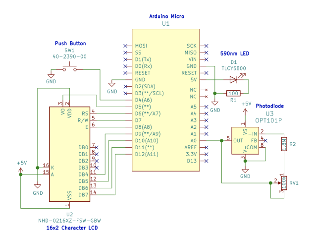
I am trying to rebuild a device and have wired everything according to the schematic:
You can see that the output pin of the photodiode (pin 5) is connected to the ADC pin A0 of the Arduino. By adjusting the potentiometer, I should of course get values between 0 – 1023 (10 bit ADC). However, no matter how I adjust the potentiometer, I always get 1023, so I think the sensor is “overshooting” all the time. I have tested the potentiometer previously and it works fine. I suspect there is something wrong with the wiring diagram.
Any ideas? Thanks in advance.


In the circuit i cant see where the arduino is connected to the power source
If you’re consistently getting a value of 1023 from the ADC, it suggests that the voltage at the ADC pin is always at or near the maximum (5V for a typical Arduino). Here are a few things to check:
i also suggest you check the datasheet of the photo diode to confirm the manufacturers requirements
CONTRIBUTE TO THIS THREAD