Become a leader in the IoT community!
New DevHeads get a 320-point leaderboard boost when joining the DevHeads IoT Integration Community. In addition to learning and advising, active community leaders are rewarded with community recognition and free tech stuff. Start your Legendary Collaboration now!


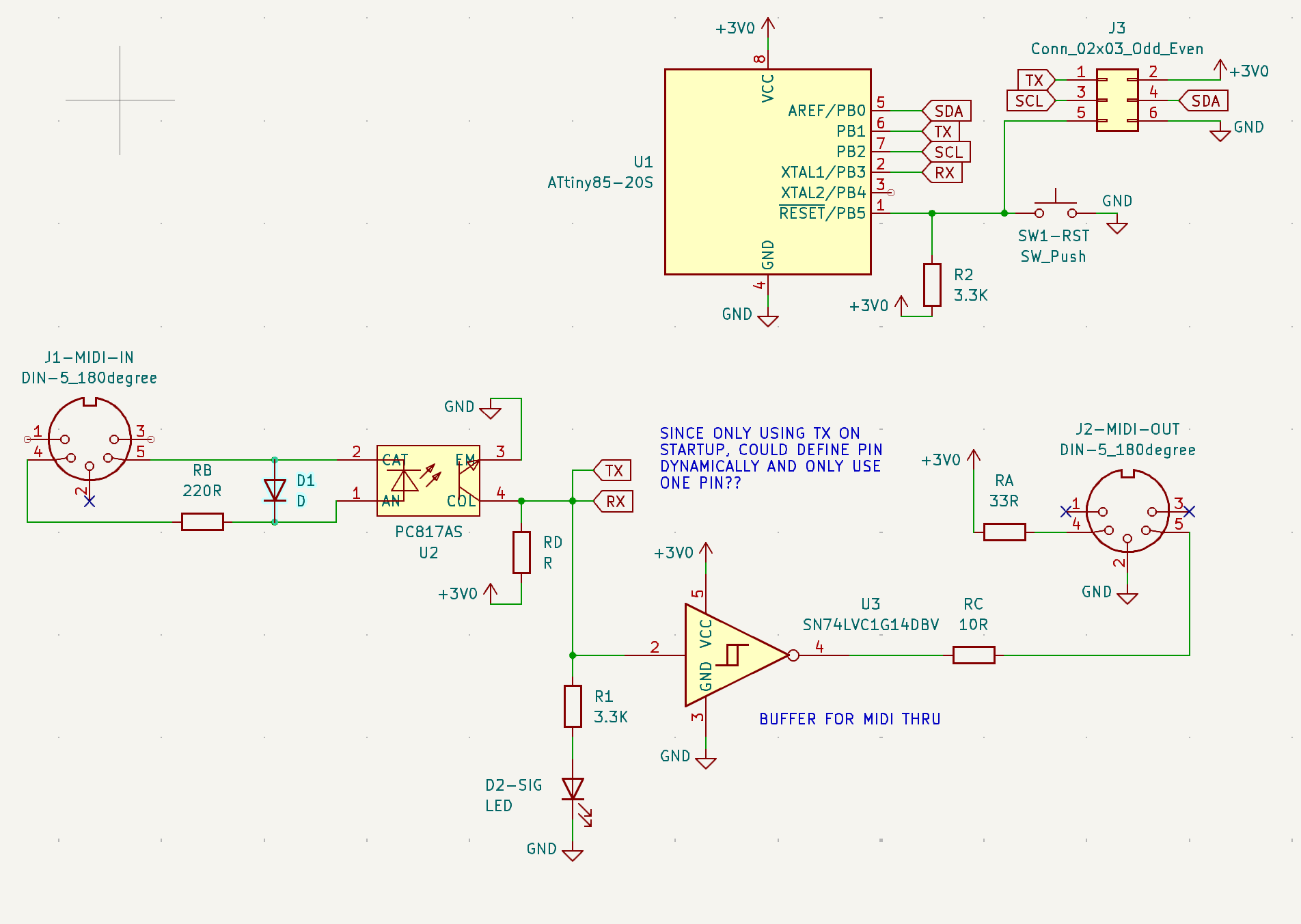


Alright, here’s what I’ve come up with so far.
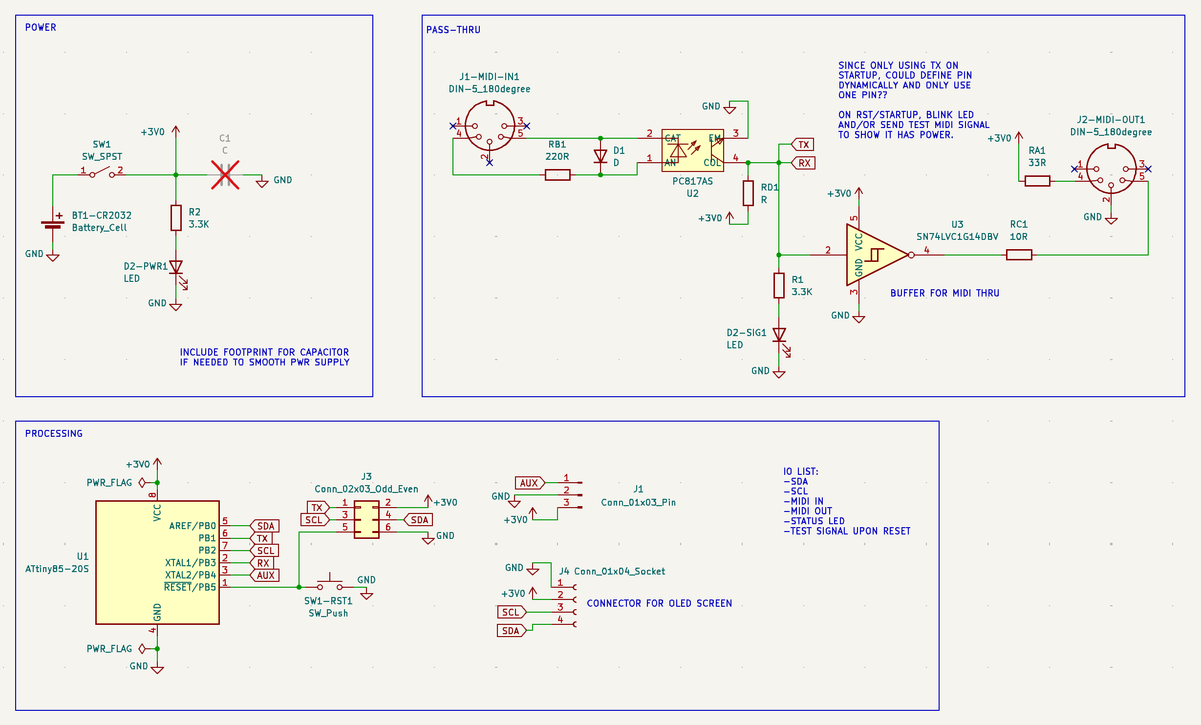
Images: Mecanical CAD, schematic, PCB design, PCB 3D Model.
Was hoping to not have a power switch and just use the reset pin to activate the ATtiny microcontroller, but I’m using an OLED which draws ~5mA when power is applied and nothing is lit up.
Using separate pins as Rx and Tx. Open to any suggestins!
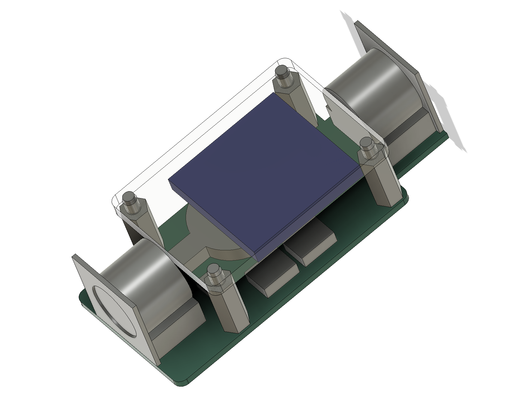
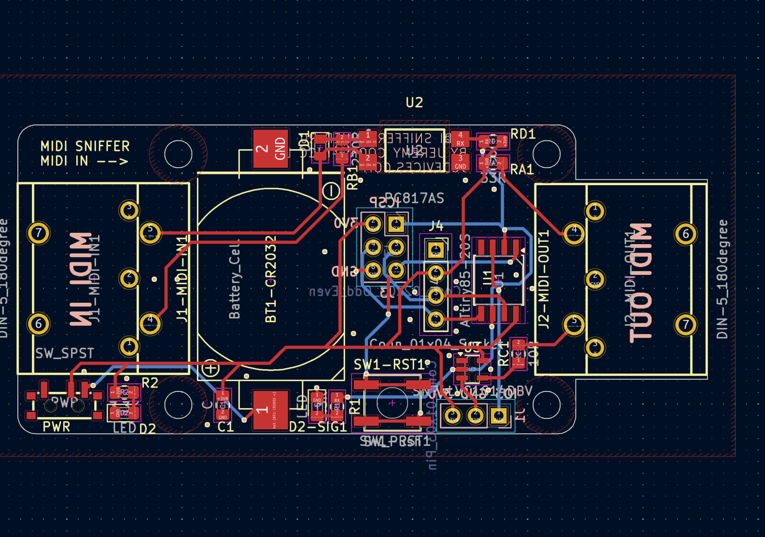
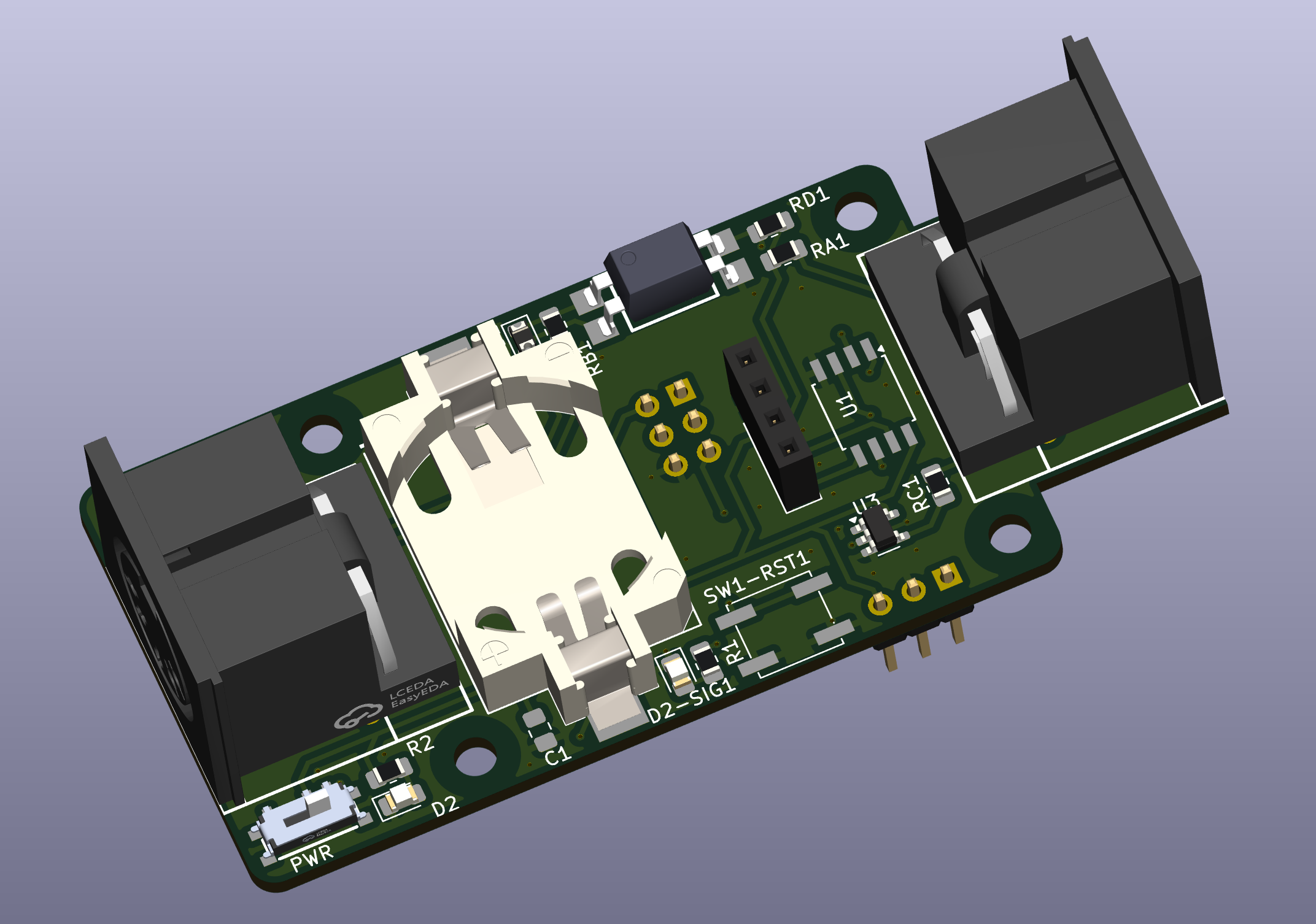
Got my device on order with JLCPCB. It will come with most of the SMD devices soldered on, 5 of these boards, for less than $50 including shipping (using a few cupons that came up). Assuming it comes back as I’d hope an expect that is an incredibly good price and will save me a ton of assembly time (though setting things up did take some time).
While they’ve offered, I am not sponsored by JLCPCB, but have been by other board manufacturers. My gut feeling so far is that JLCPCB has the most to offer from what I’ve seen.
They didn’t have the buffer I wanted available, so I also included a solder bridge that I can connect as needed. Per some previous comments, I think it will work without it. A good design change IMO. I am excited to see how this works out!
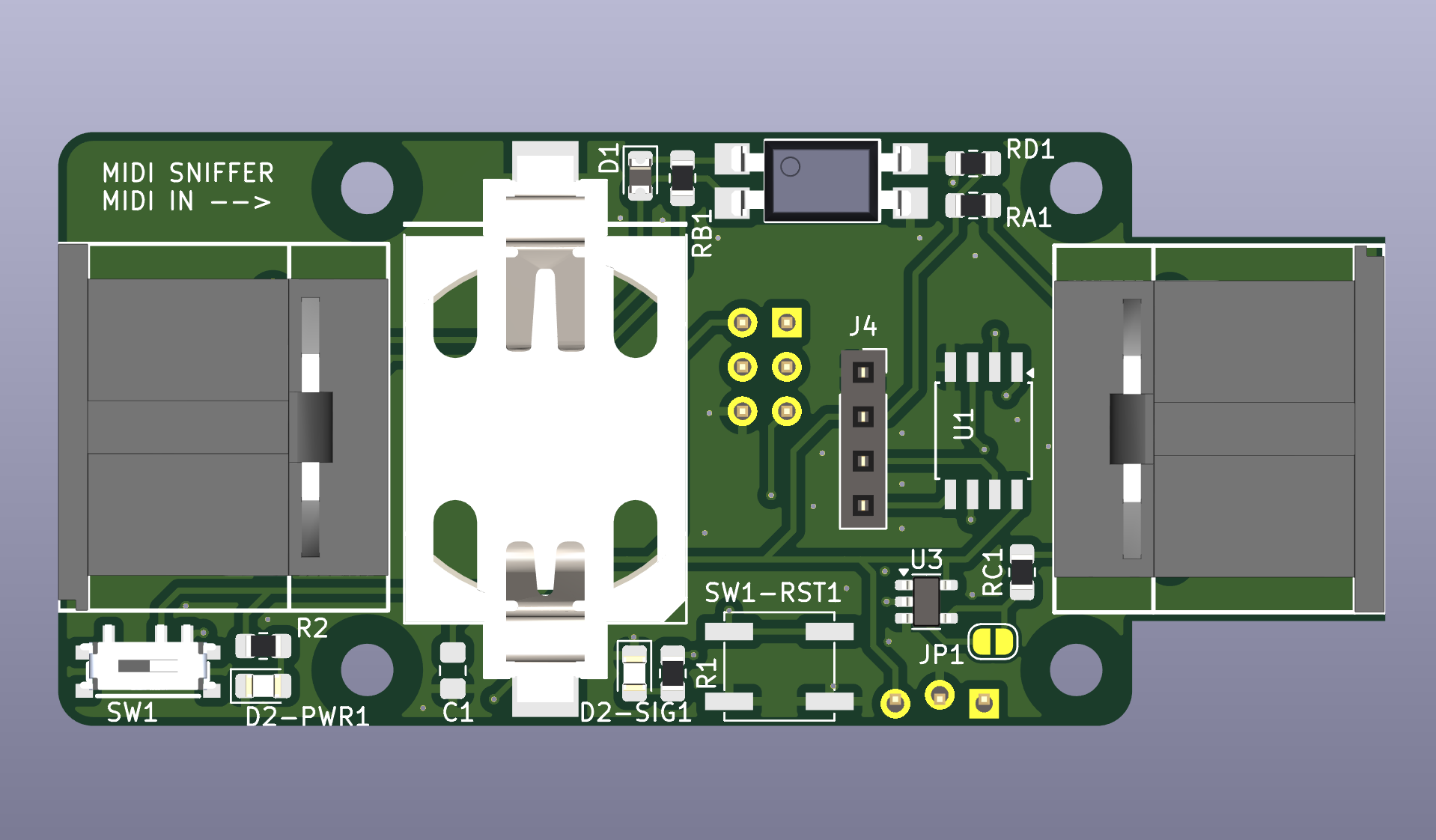
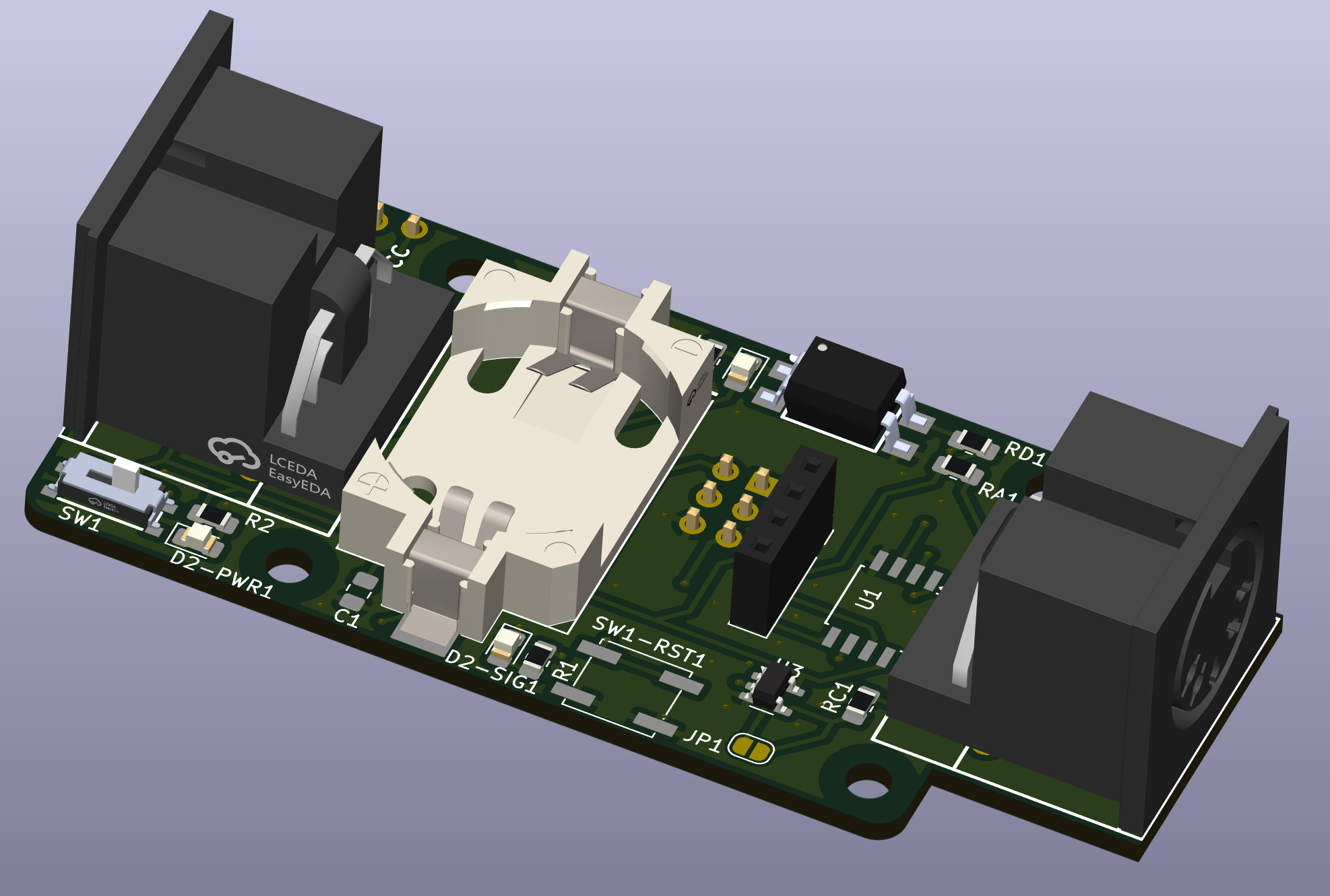
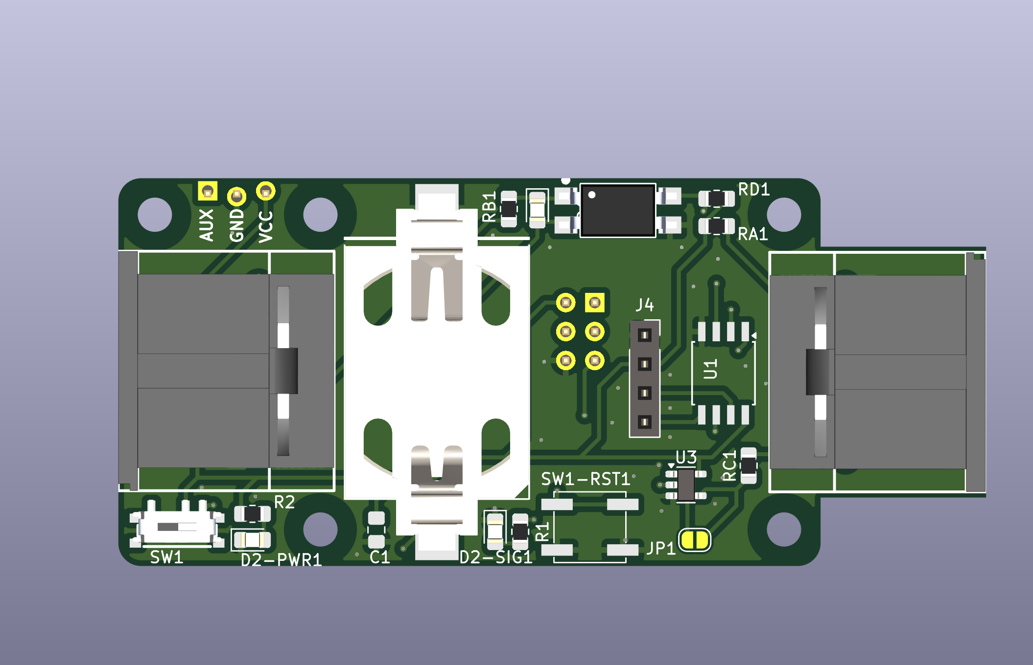
My first try came back with a question about the opto-isolator orientation (the big black component toward the upper-right on the design). Turned out it looks like I’d made a mistake mirroring the symbol in the schematic, which doesn’t really work once you get to the PCB stage as you can’t actually mirror a component in real life.
Was an inconvenience to correct, HOWEVER, it also gave me an opportunity to move the aux pins to the upper-left, and add a screw hole to help secure add-ons and/or for mounting.
I guess the lesson is take advantage of opportunities when they come and/or wait a day or two before actually ordering your PCB/PCBA!
CONTRIBUTE TO THIS THREAD