Become a leader in the IoT community!
Join our community of embedded and IoT practitioners to contribute experience, learn new skills and collaborate with other developers with complementary skillsets.

Join our community of embedded and IoT practitioners to contribute experience, learn new skills and collaborate with other developers with complementary skillsets.


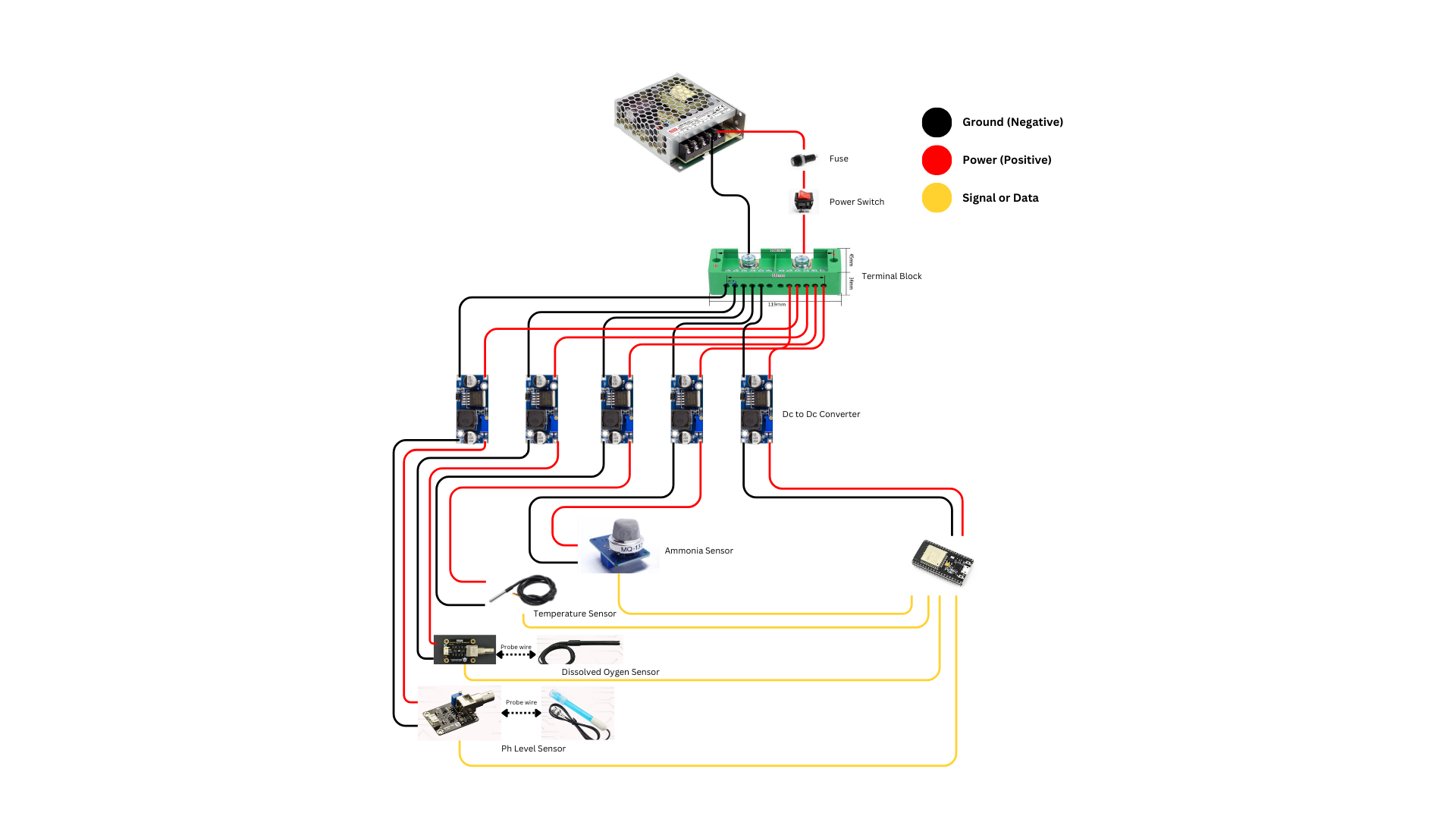
hello everyone i am trying to create a water monitoring and here is my draft is it okay or do you guys have suggestions? the ammonia sensor is temporary because I cant find a water based sensor for ammonia right now. I am new on iot btw


What aspect of the design are you questioning/looking for validation on? The overall architecture? If looking for overall architecture validation @umeshlokhande may be able to comment; otherwise, please specify.
I want to know know if all the sensors will work with that design sir
Its my first time to make a project with iot
Please check the exact datasheet of the chosen sensors to ensure the operating voltage I can see some chosen sensors operate on 5V DC & some operates on 3.3V. Once you sort out this then I suggest to rethink the architecture because one DC-DC Converter will be good enough for powering entire circuit. (i appreciate if you provide more details like exact names, tech specs of sensors etc)
This is all my components sir for prototyping. @umeshlokhande
Microcontroller: Esp32 38 pins – 3.3V
Gravity Analog pH Sensor – 3.3~5.5V
Ammonia Sensor MQ-137 – 5V
Temperature Sensor: DSI8B20 – 3.0V~5.5V
DFRobot Gravity: Analog Dissolved Oxygen Sensor – 3.3~5.5V
Great, just use one DC-DC Converter for powering an ESP32 Dev Board (If you want to avoid USB). *Try use original esp32 dev board for accurate voltage which leads to stable sensor values on sensor connected pins*. Since ESP32 support both 3.3V and 5V pins. You can power all sensors from these pins itself. Best wishes!
can i direct the ground and power to the esp32 sir? @umeshlokhande
I saw some people having problems with step-down converters, especially with the 3.3V output for the ESP32. I think it might be better to use a 5V supply for the ESP32 and rely on its internal regulator. I’m not sure if this problem is common or not, and you don’t necessarily need a separate step down for each component.
Thanks, mohamed. Where are you seeing the ESP32 issues. Can you point?
I saw this issue discussed in a private WhatsApp group for embedded systems. Although I’m not sure about the exact outcome, they mentioned that connecting the ESP32 to a 3.3V step-down converter caused something to burn on the ESP32. I think the problem might have been with the step-down converter itself—possibly because it was faulty, damaged, or not an original LM2596 module.
heh, great to know. Thanks for sharing.
What’s your story where are you from/work?
I’m Mohamed, a computer science student. I don’t have much practical experience yet, so I’m trying to gather as much information as I can. What about you?
Here’s a video as well, in case anyone needs to see the problem. I think it might help.
You should avoid doing it. In ideal scenario use of step-down converter. I’m not sure the purpose why you’re using external power supply but still. In your question, I hope you’re refering power as vcc because on the other hand you mentioned ground. Please check specifications of your power supply and spend sometime to learn about selecting power supply and circuitry that suits to your project requirements. Hope this help!
CONTRIBUTE TO THIS THREAD